Understanding the space communication basics is essential to know how satellites, spacecraft, and ground stations exchange information. Radio signals are the backbone of this process, and their behavior depends on physics, frequencies, and system design. Let’s explore the fundamentals of radio, propagation, modulation, and noise that define how communication works in space.
Electromagnetic waves and frequencies in space communication
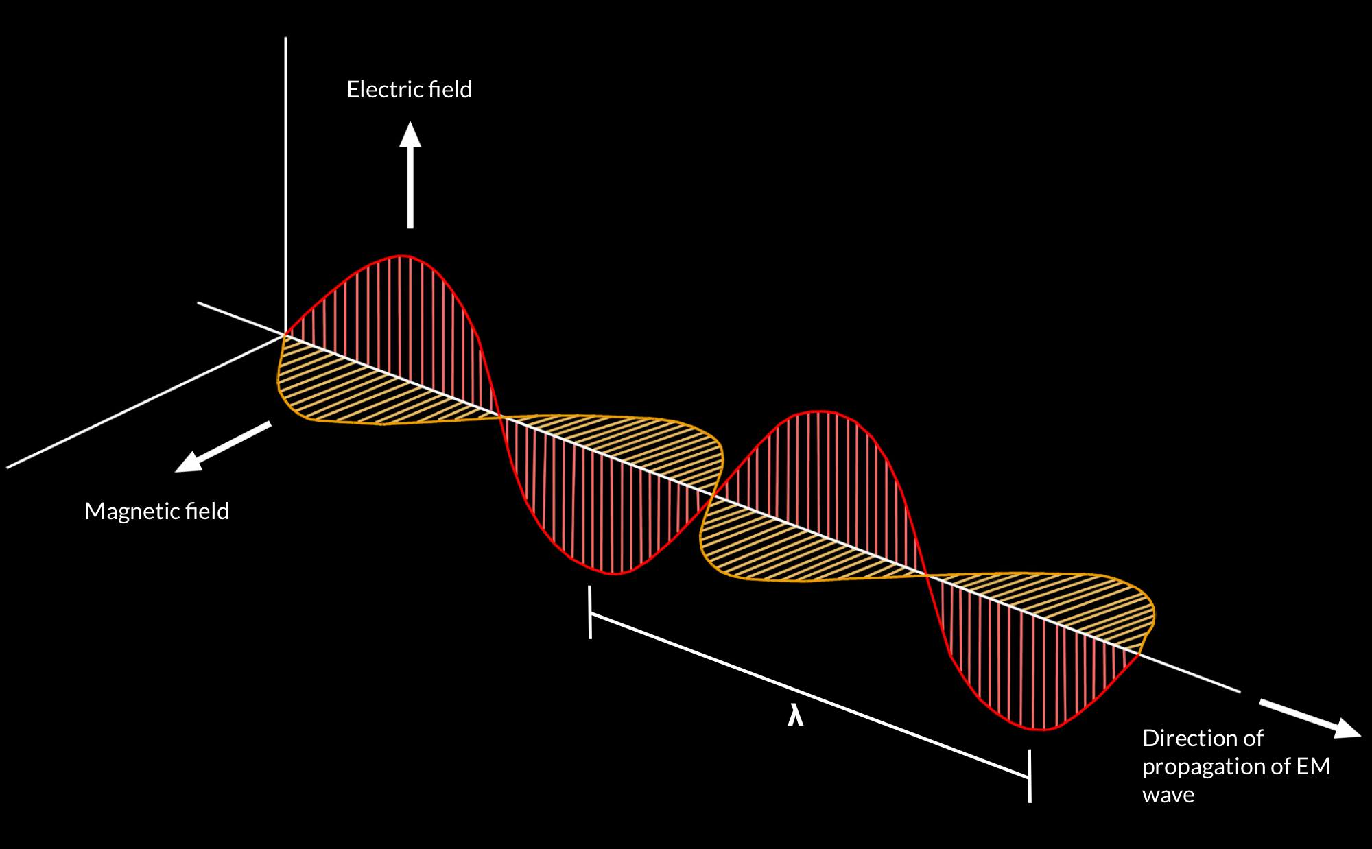
Space communication relies on electromagnetic waves, a form of energy that travels through space at the speed of light. These waves are created when an alternating current oscillates in a conductor. An easy way to picture it: imagine invisible ripples traveling through space, made of an electric field and a magnetic field that oscillate together.
The frequency (in Hertz, Hz) indicates how many oscillations occur per second:
– Kilohertz (kHz) = 1 × 10³ Hz
– Megahertz (MHz) = 1 × 10⁶ Hz
– Gigahertz (GHz) = 1 × 10⁹ Hz
The wavelength of a signal is inversely proportional to its frequency:
– High frequencies → short wavelengths.
– Low frequencies → long wavelengths.
Example: A 900 MHz signal has a wavelength of about 33 cm.
Everyday analogy: Wi-Fi at home (around 2.4 GHz) has a shorter wavelength than FM radio (around 100 MHz). That’s why radio passes through walls more easily than Wi-Fi.
Gain, loss, and attenuation (Decibels explained)
In radio systems, signal strength changes as it passes through different components. We measure this with decibels (dB).
- Level: signal strength, typically measured in watts (W).
- Gain: when a signal is amplified. Example: a gain of +10 dB means the power increased tenfold.
- Loss/attenuation: when the signal weakens, e.g. in cables or through the atmosphere.
Decibels express ratios:
– Power ratio → 10 log₁₀(P₂/P₁)
– Voltage ratio → 20 log₁₀(V₂/V₁)
Common references:
– dBm: relative to 1 milliwatt
– dBW: relative to 1 watt
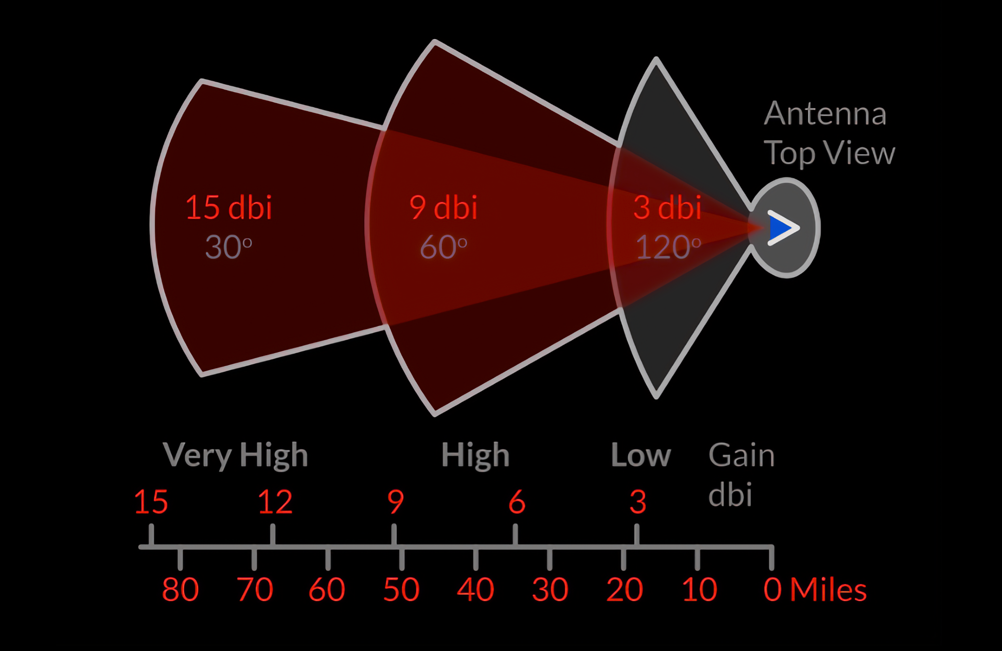
– dBi: antenna gain relative to an isotropic radiator (idealized antenna radiating equally in all directions)
Why use decibels? They make comparisons simple.
Example: If a radio receives 1 watt and another signal of 0.1 watt, instead of saying “one is ten times weaker,” engineers just say it is –10 dB.
Propagation modes of radio waves
One of the most challenging aspects of space communication basics is understanding wave propagation—how radio signals travel and interact with the environment.
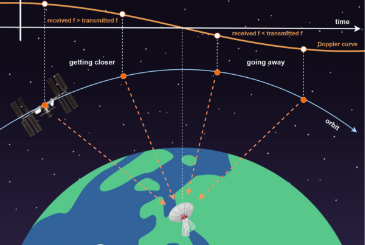
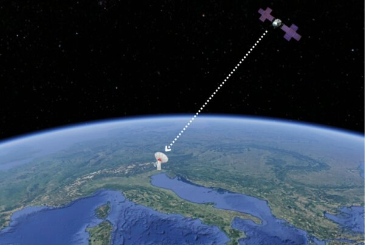
Line of Sight (LOS) in Space Communication
Most space communication systems operate in line of sight, where transmitting and receiving antennas must have a clear view of each other.
– Limitation: Free-space path loss increases with both distance and frequency.
Everyday analogy: LOS is like using a flashlight—you need a direct, unobstructed path for the light (or signal) to reach the receiver.

Ground wave propagation
At very low frequencies (10–30 kHz), radio waves can travel along Earth’s surface.
– Used in submarine communications
– Can penetrate solids, but not used for space missions
Example: AM radio at night can be heard much farther than during the day, partly because ground and sky waves help it travel beyond the horizon.
Sky wave (ionospheric mode)
High-frequency (HF) signals can reflect off the ionosphere, enabling long-range communication on Earth.
– Useful for terrestrial comms but too noisy for spacecraft
Example: Amateur radio operators (“ham radio”) use this to talk with people on the other side of the world without satellites.
For space missions, line of sight propagation is the primary mode, but knowing other modes helps in understanding possible interference sources.
Modulation and demodulation in space communication
To send information over radio waves, data is added to a carrier wave through modulation. At the receiver, the data is extracted via demodulation.
- Amplitude Modulation (AM): carrier amplitude varies with the signal.
- Frequency Modulation (FM): carrier frequency varies.
- Phase Modulation (PM): carrier phase varies.
Everyday analogy:
– AM is like raising or lowering your voice’s volume to send information.
– FM is like changing the tone of your voice slightly.
– PM is like speaking with tiny shifts in rhythm.
Modern space communication systems use digital modulation with error correction coding to ensure reliable data transfer across vast interplanetary distances.
Signal-to-Noise Ratio (SNR) in space systems
The Signal-to-Noise Ratio (SNR) compares the desired signal strength to background noise. A higher SNR means clearer communication and fewer errors.
- Performance margin = Output SNR – Required SNR
- In deep space missions, system noise is modeled as:
N₀ = kT
where k = Boltzmann’s constant and T = system equivalent noise temperature
Everyday analogy: SNR is like trying to hear someone speaking in a noisy room. If their voice is much louder than the noise, you understand them clearly. If it’s almost the same level, you miss words or whole sentences.
Maintaining a good SNR is critical to ensure that even weak signals from millions of kilometers away can be received and decoded.
Conclusion
Mastering the space communication basics means understanding radio signals, frequencies, decibels, propagation, modulation, and noise. These fundamentals form the backbone of every space mission, from satellites in Earth orbit to spacecraft exploring the outer planets. By applying these principles, engineers design communication systems that keep humanity connected to the cosmos.
INTREPID ground station antenna systems for space communication
If you are looking to own a ground segment for radio frequency space communications, you should choose the INTREPID ground station antenna systems that are designed with different antenna dimensions and for various radio bands. If you want to know more about our INTREPID ground station antenna systems, you can click here and discover all the available models. In order to allow everyone start his project, PrimaLuceLab also offers design, shipment, installation and training services: we can support you from design to shipment, from installation to on-site training.